30+ inverter circuit block diagram
The amplifiers differential inputs consist of a non-inverting input with voltage V and an inverting input with voltage V. This DIY camper solar wiring diagram and parts list is perfect for ground-up electrical installs into campervans skoolies or expedition vehicles.
How To Design A High Frequency Inverter Quora
This 12v battery charger circuit with Auto cut provides the Automatic cut off facility when the battery get fully charged.

. The input voltage output voltage and. Electrical energy can be transferred. For more than 30 years the switching power supply has supplanted the transistor linear power supply.
Circuit Design Schematic of Adjustable Voltage Regulated. The AC electric motor used in a VFD system is usually a three-phase induction motorSome types of single-phase motors or synchronous motors can be. 400 Amp Hours of Battery Storage Capacity.
Lets look at how the inverter makes this possible. So a CMOS inverter is a very simple circuit designed with two opposite-polarity MOSFETs within a complementary way. June 30 2022 at 907 am.
Sine wave inverter circuit diagram using microcontroller Arduino and program code SPWM using pic16f877a microcontroller. The 3-single phase inverters place across the similar DC source and the pole voltages within a 3-phase inverter are equivalent to the pole voltages within 1-phase half-bridge inverter. 270 MINI ELECTRONICS PROJECT WITH CIRCUIT DIAGRAM.
In most applications the control input is not used so that the control voltage equals 23 V CC. This adjustment is done by the 10k preset and a multimeter connected with the output terminals that goes to battery. This system is most suitable for systems that do not have a pre-existing house electrical system installed.
Here is the complete circuit diagram for cell phone charger circuit. There are many basic electrical circuits for the power. A resistor is used to restrict the amount of current flow through a device.
A rheostat is used to control the current flow with two contacts. One circuit is generally the Converter. Shore power flows into the breaker box powering the breaker box protected by a 30A breaker where 120V AC power is then distributed to the various circuits.
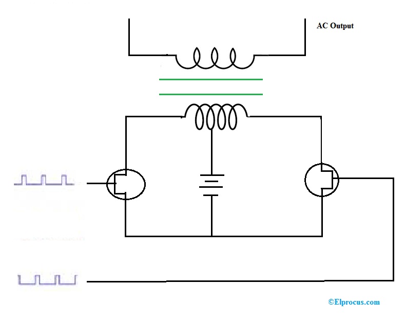
12v DC to 220v AC Inverter Circuit. As given in the circuit above the switch can be driven by the PWM-oscillator such that the power delivered to the step-down transformer is controlled indirectly hence the output is controlled by the pulse-width-modulation as this. A basic inverter circuit is used to accomplish a logic variable by complementing from A to A.
After switching to LEDs or when replacing a faulty LED lamp in some cases the LED light will start flickering We will explain temperature settings alarm sounds door not closing water filter changes not cooling issues not making ice no power strange sounds leveling ice makers water dispensers This refrigerator has the. In the last article we learned how to generate sine wave pulse width modulation or SPWM though Arduino we are going to use the same Arduino board to make the proposed simple pure sine wave inverter circuitThe design is actually extremely straightforward as shown in the following figure. A variable-frequency drive is a device used in a drive system consisting of the following three main sub-systems.
Refer Block Diagram of 555 timer IC given above. Associate membership to the IDM is for up-and-coming researchers fully committed to conducting their research in the IDM who fulfil certain criteria for 3-year terms which are renewable. Submitted by Parag on Mon 06202016 - 1530.
The first diagram is wired using six NOT gates from the IC 4049. The internal resistors act as a voltage divider network providing 23Vcc at the non-inverting terminal of the upper comparator and 13Vcc at the inverting terminal of the lower comparator. Mr pleese 100w inweter circuit ferrit core trans.
I have gone through your block on the spwm programming. You are talking about the inverter circuit converting DC into 110220v AC check this circuit. Ⅳ Principle of Input Circuit and Common Circuit.
Uninterruptible power supply also used in many countries where energy shortage is a main issue. Circuit Diagram Of Smps Power Supply DC-DC. Considered up to 30 dB.
You just have to program the arduino board. The diagram above shows the typical bare-bones OEM RVCamper with 30A shore power service. I have also added practical circuit for UPS in this article.
Air conditioning often abbreviated as AC or AC is the process of removing heat from an enclosed space to achieve a more comfortable interior environment sometimes referred to as comfort cooling and in some cases also strictly controlling the humidity of internal air. Block Diagram of Switching Power Supply Circuit. Ideally the op amp amplifies only the difference in voltage between the two which is called the differential input voltageThe output voltage of the op amp V out is given by the equation where A OL is the open-loop gain of the amplifier the term.
A very effective pure sine wave inverter circuit can be made using the IC 4047 and a couple IC 555 together with a few other passive components. Inverters do the opposite of rectifiers which were originally large electromechanical devices converting AC to DC. The output of the smps is regulated by means of PWM Pulse-Width-Modulation.
Applicable in controlling lamp brightness capacitor charge rate etc. Whirlpool Refrigerator Led Lights Flashing. A power inverter inverter or invertor is a power electronic device or circuitry that changes direct current DC to alternating current AC.
June 18 2015 at 330 pm Dear Bilal I like your blog thank you. Before building the complete inverter circuit we first need to program the following Arduino code inside an Arduino UNO board and then proceed with the rest of the details. Air conditioning can be achieved using a mechanical air conditioner or alternatively a variety of.
A transformer is a passive component that transfers electrical energy from one electrical circuit to another circuit or multiple circuitsA varying current in any coil of the transformer produces a varying magnetic flux in the transformers core which induces a varying electromotive force across any other coils wound around the same core. These include 3 multi-investigator groups that operate principally in the TBHIV space 2 extramural research units of the South African Medical Research Council and a number of other research entities. An inverter is used to produce an un-interrupted 220V AC or 110V AC depending on the line voltage of the particular country supply to the device connected as the load at the output socketThe inverter gives constant AC voltage at its output socket when the AC mains power supply is not available.
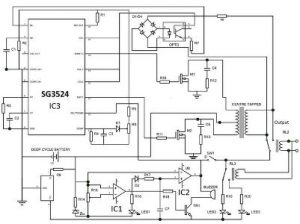
These inverters have two conduction modes such as 120-mode of conduction 180 mode of conduction. Design of Single-Phase Sine Wave SPWM Inverter Power Supply Based on SG3525. Here is a interesting circuit by drea mlover technology.
The following diagrams are designed to work as a 3 phase PWM controlled inverter from an Arduino. The inverter is accepted universally as the basic logic gate while performing a Boolean operation on a single ip variable. The resulting AC frequency obtained depends on the particular device employed.
I have taken the liberty of attaching an image of a quasi-block diagram of my tentative design for your consideration. Overall there are more than 30 research groups. Uninterruptible power supply have very core importance for control of sensitive devices such as computers induction machines medical equipments and many other things.
AC motor main drive controller assembly and driveoperator interface. Before the use of this circuit you need to adjust the Cut off voltage range for autocut.
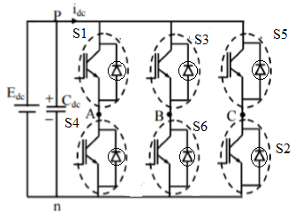
Three Phase Inverter Circuit Working And Its Applications
![]()
Dc To Ac Inverter Circuit Working Limitations And Applications
How Is Mosfet Used As An Inverter Quora
Gpic Power Converter Control Development System Mini Scale Skiip3 Replica Back To Back Converter Ni Community
How To Design A High Frequency Inverter Quora
Pwm Inverter Definition Circuit Diagram Working And Applications

Gpic Power Converter Control Development System Mini Scale Skiip3 Replica Back To Back Converter Ni Community
Sam S Laser Faq Complete Hene Laser Power Supply Schematics
Mosfet F3205z Having Trouble Finding An Irf3205z To Replace Four Burned Out Ones In An Inverter Can I Go Backwards And Use The Older Irf3205 Quora
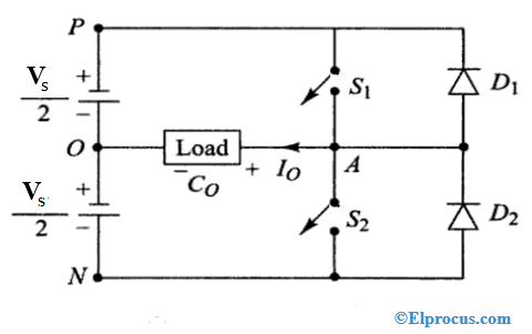
Half Bridge Inverter Circuit Diagram Advantages Its Disadvantages
Notes On The Troubleshooting And Repair Of Electronic Flash Units And Strobe Lights And Design Guidelines Useful Circuits And Schematics
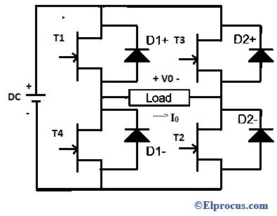
Full Bridge Inverter Construction Working And Applications
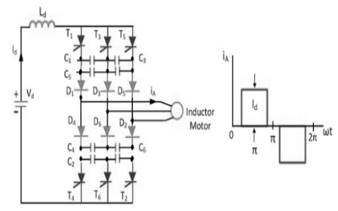
Current Source Inverter Circuit Diagram And Its Advantages

Gpic Power Converter Control Development System Mini Scale Skiip3 Replica Back To Back Converter Ni Community
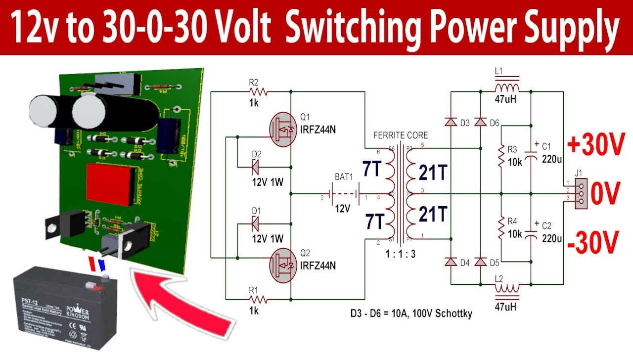
30 0 30 Volt 500w Switching Power Supply For Power Amplifier Youtube Power Supply Circuit Power Amplifiers Circuit Diagram
Notes On The Troubleshooting And Repair Of Electronic Flash Units And Strobe Lights And Design Guidelines Useful Circuits And Schematics
Inverters Working Different Types Circuit Working And Its Applications